James Schidlowsky: Handmade Electronics
Dabbling in DIY/handmade electronics since 2010. This page is a little gallery of some of my builds of
sound boxes, light boxes, and other things, with some construction details including breadboard prototypes, layouts, circuitboards, wiring, etc.
Original inspirations & impetuses: Science Fair 75-in-1 Electronic Project Kit,
Annette Peacock,
Efrim Manuel Menuck's A 12-Pt. Program For Keep On Keepin' On,
Nicolas Collins' Handmade Electronic Music book.
Ongoing inspiration: electro-music.com DIY Hardware and Software forums
(where I'm known as “RingMad”).
This is a selection. Note that many photos can be clicked on to display a larger version thereof.
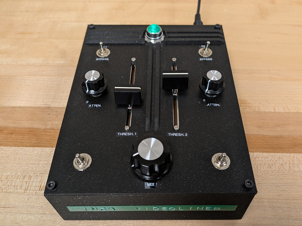
IMCA videoLiner
April 2026. Made for students in the
Intermedia/Electronic Arts programme at Concordia University, as another analog video-mangling toy.
This is basically two Vidiffektors (A.K.A. CMP-DIV Video Effecter) which go into the famous
dirty video mixer
by Karl Klomp.
The effecter circuit has been simplified, getting rid of the extra switches and potentiometers, which turned out to be unnecessary
(a fact which I discovered by accident!)
It's housed in a an Art Deco inspired box, which I designed and had 3D printed.
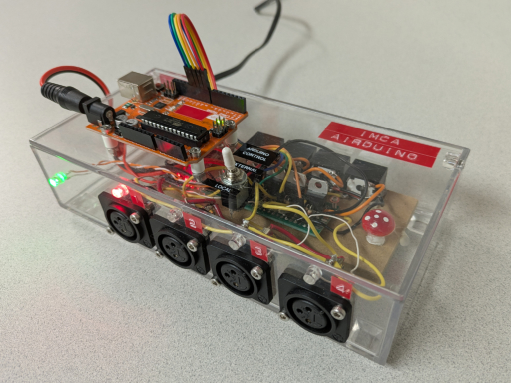
IMCA AIRduino
March 2026. Made for the IMCA322 Robotics for Artists course in the
Intermedia/Electronic Arts programme
at Concordia University.
Instead of a big, heavy control box controlled via MIDI, this provides a lighter alternative. It can control up to 4 solenoid air valves for
pneumatics/compressed air. The onboard Arduino can be programmed for whatever sequences or timings are required for a given project.
A switch enables the onboard Arduino to act as a "through" device so that it simply passes along logic level control signals from an
external Arduino or circuit.
Neon Flasher Box
April 2021. A simple flasher box to control an electronic neon transformer. Built using the classic 555 timer chip and solid state relay.
The circuit allows one to change the mark & space time up to 4 seconds each (i.e. adjustable duty cycle).
Made for Montreal neon bender & artist François Alfred Mignault.
1973 Kiss-a-Scope Restoration/Modification
November 2018. The Kiss-a-Scope “love tester” was manufactured as part of the fall 1973 lineup of arcade games
by Urban Industries Inc. of Louisville, Kentucky and brought back to life (and improved?) by Jordan Bowden
and James Schidlowsky in 2018 for operation at the
North Star machines à piastres bar
in Montreal, Canada.
Click through to the Kiss-A-Scope Information page for more details and
some interesting history behind it.
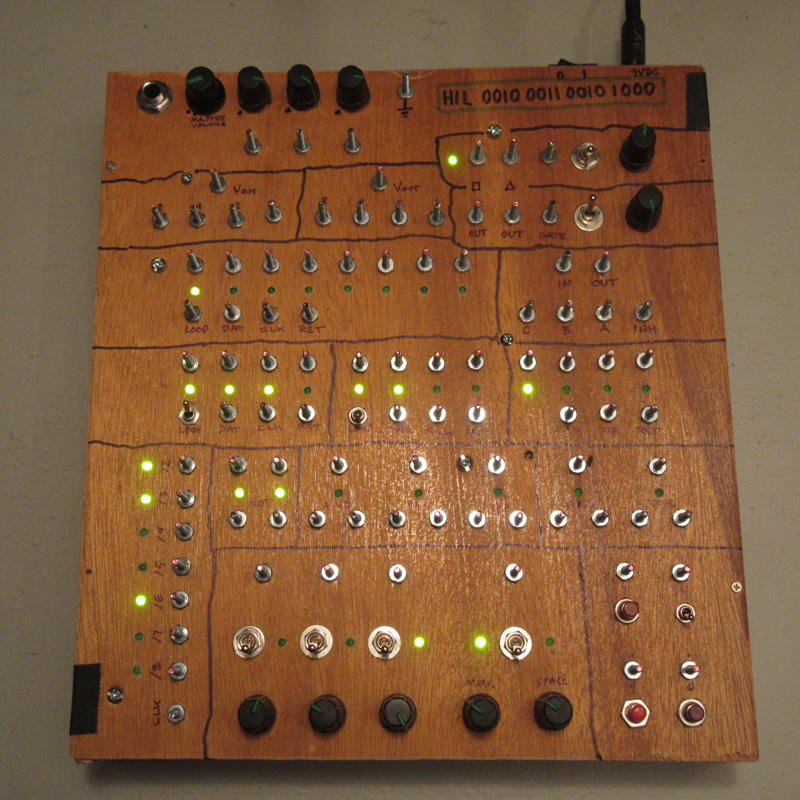
HIL 0010001100101000 (prototype "Lunetta" synth)
September 2017. A temporary "box" built in a hurry for use in an
audio-visual performance at the Mixed Input Festival
organized by Pleasure Dome in Toronto.
It's pretty much a Lunetta-style synth,
mostly made using CMOS logic chips.
(HIL for Highly IlogicaL,
or maybe Highly Interesting Logic,
and the binary number is another reference)
From top to bottom more or less:
- 3-input mixer
- 2 x 4-bit R2R DAC
- 2 gate-able square & triangle oscillators w/ 2 ranges
- 8-bit 4015 shift register
- 4017+4051 "melody generator"
- 2 x 4-bit 4015 shift registers w/ loop switch
- 4029 up/down binary counter
- Logic section: 2 x NOT, 3 x AND, 2 x XOR gates
- Ken Stone's CGS Pulse divider (w/o logic section or reset)
- 3 clock oscillators w/ 2 ranges
- 1 mark & space (variable duty cycle) oscillator w/ 2 ranges
- "bit buttons", i.e. momentary switches, 2 connected to 9V and one connected to ground. Also, 9V connected to on/off switch.
I think there are 94 bolts. It's a little bit cramped.
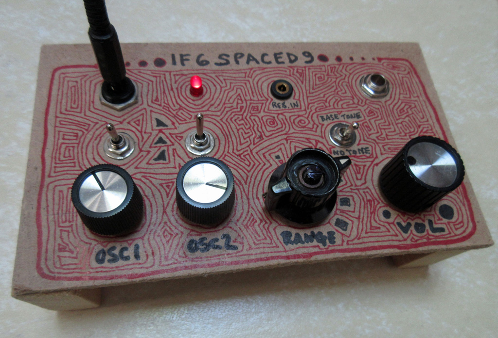
if6spaced9 (temporary "box")
May 2017. A temporary "box" for a circuit that will be expanded into a proper box, once some subcircuits are
perfected. In the meantime, I needed to get it off the prototype boards and playable in a live situation.
The circuit is a slightly expanded version of my
Bag Balm Box, specialized for use
with a resistive ribbon controller.
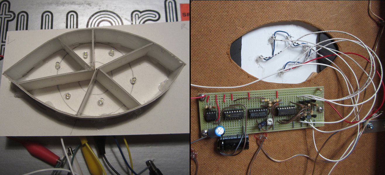
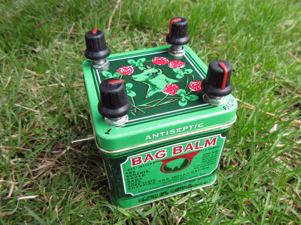
Bag Balm Box
The Bag Balm Box is "for bunches, caked bags, cuts, sore teats, chapping and inflammation".
Bag Balm is a salve developed over 111 years ago to soothe irritation on cows' udders after milking but also used by humans for dry, chapped skin. I loved the container artwork, so after finally finishing the contents (which took several years), I decided to put in a little sound-making circuit, which is a slightly tweaked version of the Space4069 schematic by Synaesthesia on electro-music.com. It uses CMOS 4069 to generate waveforms which feed a 4046 VCO.
Two potentiometers on the left control the oscillator rates, two 3-position switches on each side to control the wave shapes of each (sawtooth, triangle, reverse sawtooth), plus frequency and volume controls. On the back, the on/off switch, the range switch (high, low), and the output jack. Through the eye of the cow, a white LED indicates that the power is on (9V battery).
I was thinking of somehow making some knobs that looked like cow udders, but got lazy because I have many other projects on the pile.
Completed April 2017.
Here is the Bag Balm Box demo video.
CLK-OSC Module
January 2017. A simple clock oscillator module for a collective semi-Lunetta-ish synth at the
Eastern Bloc soundLab in Montreal...
Some basic square wave oscillators: 2 with inverted outs as well, 1 normal, and one with mark & space control (i.e. adjustable duty cycle), all with 2 frequency ranges.
All made using a single CMOS 40106 hex Schmitt trigger inverter.
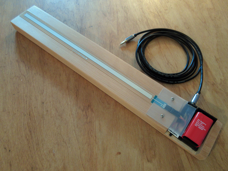
Ribbon Controller
November 2016. A ribbon controller produces a CV for use with other voltage-controlled modules by moving one's finger on the ribbon.
After building different makeshift ones using resistive video tape and a couple of different systems like suspending the tape above a strip of copper or suspending a guitar string above the tape glued to a surface, I finally gave in and bought a softpot membrane potentiometer by spectra symbol.
It's much more robust than any of my previous problematic efforts, and basically all I did was put it on a board and wired up a bit of hardware for the battery, switch and TRS jack. It can either use the power from another compatible device via the cable or from the onboard battery. A future improvement would be to add a potentiometer for attenuating the output to be more compatible with other devices.
Dual VCO
The Dual VCO is a simple box with two independent VCOs (Voltage Controlled Oscillators) in it. They can generate square,
triangle, sawtooth and reverse sawtooth waveforms in 12 different frequency ranges. Each oscillator also has a volume and a
glide (portamento) control. Both VCOs can have a separate output channels, or be mixed into a single one.
Both VCOs use the same CV input, but each can adjust the level it receives. For standalone use, it can be switched to
use an on-board potentiometer to set the CV level instead of the external input.
The box is painted metallic green (the photo doesn't do it justice), and the "on" indicator LED is a purple triangle.
Completed April 2016.
Utility Boxes: FACEMULT & HEXGĀT
March 2016. Just a couple of utility boxes that don't make sound but are handy.
FACEMULT: allows MULTiple (4) separate signals to be interFACEd between 4 styles of connector:
1/4, 1/8, banana and bolts. A bit later I added 2 RCA jacks. Handy for interfacing with other synth systems.
HEXGĀT: produces 6 simple gate/clock signals with adjustable rates (from approx 0.2 - 18 Hz)
and 1/4 jack outputs and bolts (for use with alligator clips so as to communicate with breadboards). This is simply
6 square-wave oscillators made using a CD40106 chip.

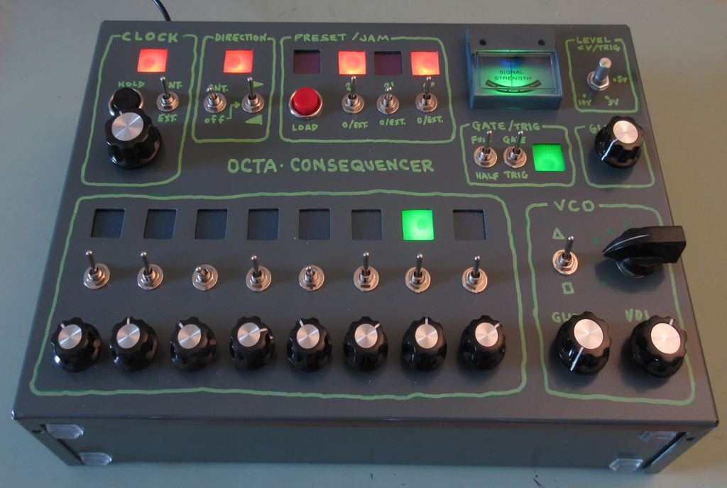
Octa Consequencer
The Octa Consequencer is an 8-step analog sequencer that outputs a control voltage (CV). It's got the usual step on/off and one
can set the CV value for each step. The clock speed can be adjusted and there is a hold button. It has a built-in triangle/square VCO
with a separate glide control and output. Other outputs are raw CV, CV with adjustable glide (portamento) and gate/trigger. The gate
has 2 flavors, either ANDed with the clock thus appearing at every step or remaining on whenever a step is on. Trigger output is the
same thing but a short pulse.
This was originally inspired by Dr. Offset's
16 step Up/Down sequencer, and then the details of the schematic filled in from other designs like like the Baby 10, MFOS.
Instead of the CD4029, I used the similar CD4516 CMOS presettable counter with a CD4051. Thus one can control the direction,
as well as reset the counter to a specified binary value. The clock, direction, preset load and preset value
can all be set by external gate signals for extra madness.
For the direction, an "antenna" mode can be selected. This basically makes the up/down pin on the counter chip floating, and
it behaves erratically/randomly and responds sometimes to moving one's hands near the box.
The square windows for the LEDs were made by hand using a nibbler tool, and then behind, isolator boxes with colored gels.
Completed February 2016.
Here is the Octa Consequencer demo video.
Animated Pinball Lightbox : Centigrade 37.
Demo video here: https://vimeo.com/150537040.
Completed December 2015.
This is an electronically animated lightbox I made from the backglass of a
Centigrade 37 pinball machine made by Gottlieb in 1977.
The original machine had an electro-mechanical animation for the thermometer, which consisted of a red ribbon that
would crawl up by increments each time one hit certain targets. Instead, I used a gradient of dark red to light
yellow printed on acetate and compartmentalised LEDs. When it reaches the top, the tower flashes faster and faster,
then the thermometer decrements back down.
I made this for my friends who opened the North Star pinball bar in Montreal
in January 2016, which is reflected in the score digits (printed on cardstock, not using actual score reels),
as well as their star logo in the credit window. This was part of the decor at the bar until July 2019,
when it was removed to make room for a neon sign for which I had made the
animation circuit and programmed.
Here are the front and back of the lightbox...
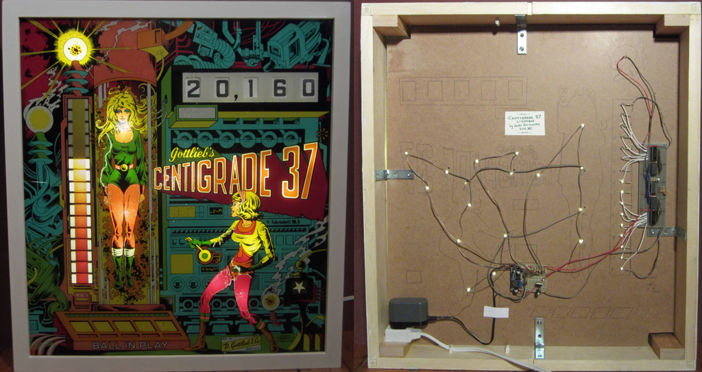
* 33 warm white "straw hat" LEDs running on 12V regulated "wall wart" power supply. 16 of them are always on,
for general illumination, 16 are for animating the thermometer, and one to flash the tower.
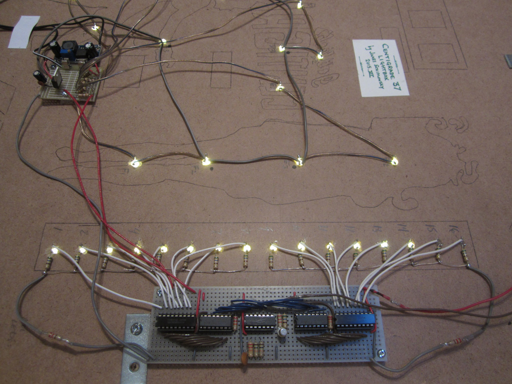
* A PICAXE-14M2 microcontroller is used in conjunction with 74HC595 shift registers and TD62783 transistor array drivers
to control the animation.
* A pre-made LM2596 buck converter board is used to drop the voltage down to 7.5V which is then fed
to an LM7805 voltage regulator to supply the PICAXE and 74HC595's.
* Some of the logic involves randomness: the length of time between thermometer gradations lighting up and the
pause before the animation sequence starts over.
Here's a close-up of the main circuit boards:
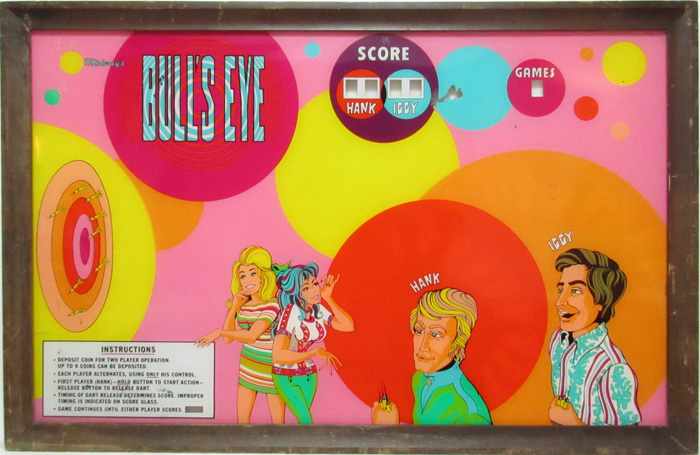
Animated Wallgame Lightbox: Midway "Bull's Eye".
Demo video here: vimeo.com/136931561. Completed August 2015.
This is an animated lightbox I made from the painted plexiglas panel and frame from a "Bull's Eye"
wall game made by Midway circa 1972. Before videogames, people used to play these. It was a 2-player dart game with hand
controls to select when to release the dart, and it would take one of 3 trajectories and hit one of several spots on the
dartboard. All I had was this piece, not the whole machine. I've only seen a photo of the original interior with a bunch of light
bulbs and the control mechanism. If you want to see the real machine working, someone posted this video on youtube.
I simplified the action and just have one player throw and the dart follows one trajectory. The bull's
eye is either hit or missed.
The original frame and artwork looks like this (approximate dimensions: 130 x 83 cm):
I built an open box frame to hold the light-panel, electronics and cardboard light isolators, and it's attached to the
artwork frame using a piano hinge and a couple of magnetic latches. Here it is with the thing open:
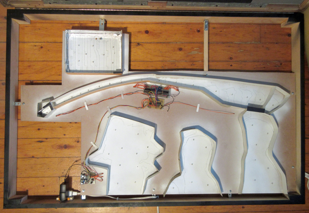
Here's the back of the light/circuit board panel, with the wiring to the LEDs:
* 49 warm white "straw hat" LEDs running on 12V regulated "wall wart" power supply. 22 of them are always on,
for general illumination, 8 are for the Bull's Eye title letters, which are usually on but also flash when the bull's
eye target is hit. The rest are for the hand and dart chasers, and the 2 possible dartboard hits.
* The 2 chasers for the hand and dart trajectory use 74HC595 shift registers and TD62783 transistor array drivers.
* A PICAXE-14M2 microcontroller is used for the logic sequence, clocking the shift registers, controlling the display of the other LEDs.
* A pre-made LM2596 buck converter board is used to drop the voltage down to 7.5V which is then fed
to an LM7805 voltage regulator to supply the PICAXE and 74HC595's. I probably could have skipped
the regulator and had the buck converter supply the 5V.
* Some of the logic involves randomness: the length of time between dart throws and if the bull's eye target is hit or missed.
Here's a close-up of the main circuit boards. The wires to the LEDs go through holes to the other side:
This and the other lightboxes I made were part of the decor at the
North Star machines à piastres pinball bar in Montreal, Canada.
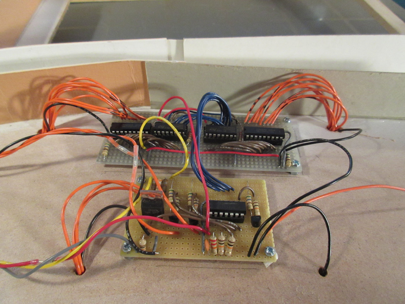
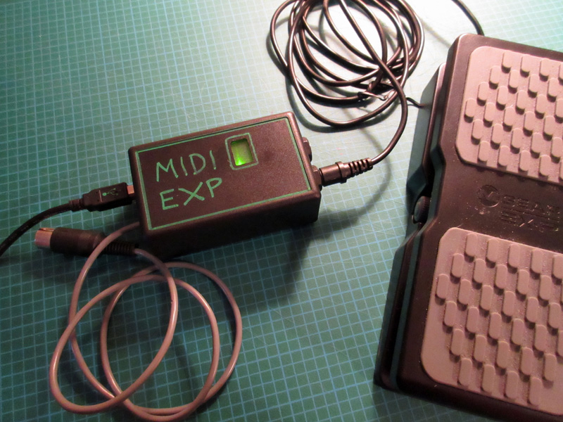
MIDI Expression Pedal Box
July 2015. A friend wanted a MIDI wah-wah, i.e. expression pedal so I whipped this up using an Arduino to process the
signal from a potentiometer-based expression pedal, and send the value along as particular control message. It was based
on this post I found on codeproject:
Arduino-Based MIDI Expression Pedal.
Instead of the pedal, one could plug in any sort of voltage-divider thing.
September 2015: New, improved version, pictured here with an M-Audio EX-P expression pedal.
Instead of the permanently-wired wallwart power adapter, I used the USB adapter. Also now can
plug in two expression pedals, thus controlling two different parameters.
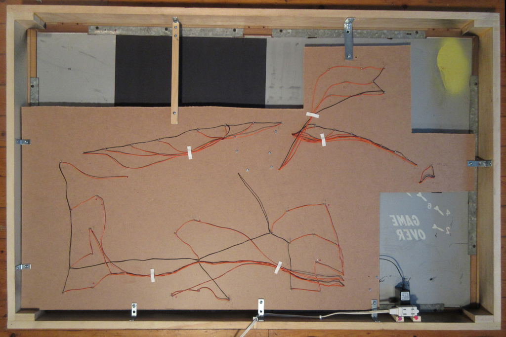
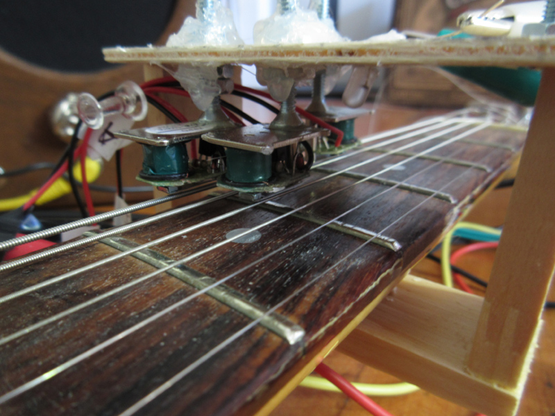
Auto-Droner Guitar (Prototype).
3 strings of an electric guitar played by electro-magnetic physical action (i.e. the strings are actually struck).
I finally broke down and used an Arduino. It controls the speed of the devices via PWM and slowly changes the
intensity of the drone.
A prototype, proof of concept, it was intended for and used as an installation at STABLE that ran for several
hours, so the variations are perhaps too subtle to capture in this brief demo video here:
https://youtu.be/1-RIjPaMFj8, June 2015.
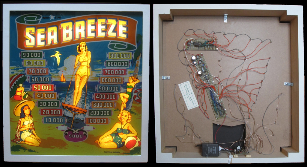
Animated Pinball Lightbox: "Sea Breeze".
Demo video here: vimeo.com/122848906. Completed March 2015
Front and back of a pinball backglass lightbox I made for friends. The electronic circuit
controls general illumination, as well as two chaser circuits, one of which changes speed periodically.
Sea Breeze
was the first of two pinball machine models ever produced in Canada, manufactured circa 1949 by the North Star Coin Machine
Company of Montreal, which you can read about in
this article. The box measures approximately
61 x 55 cm.
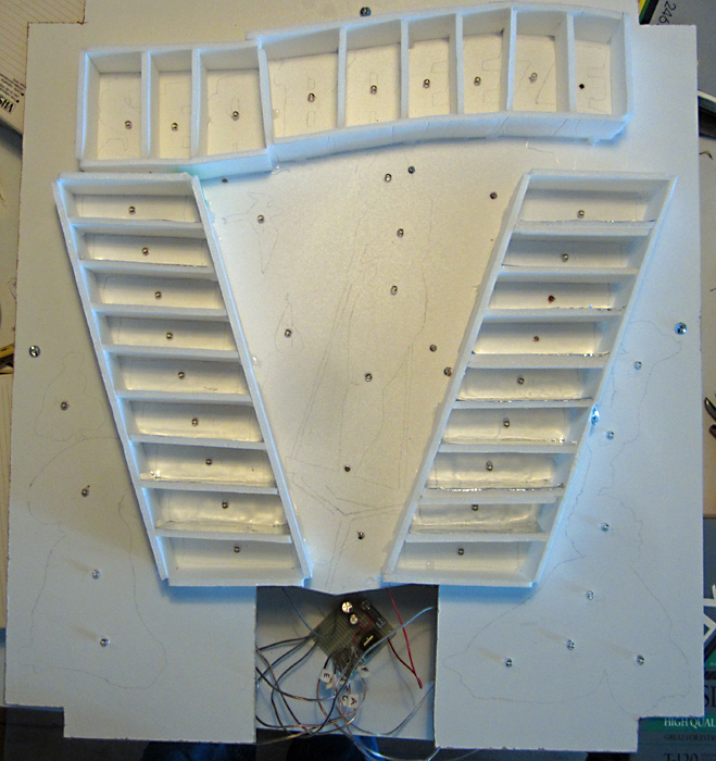
Front view of light panel with baffles. There are 45 LEDs in total: 18 for general illumination, 9 for
the S-E-A-B-R-E-E-Z-E "comet trail" chaser and 18 for the scores chaser:
Soldered boards for power and control circuits:
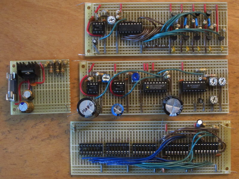
Circuit details:
* Runs on regulated 12V supply. Uses 45 warm white "straw hat" LEDs.
* The S-E-A-B-R-E-E-Z-E chaser is 9 LEDs, and was adapted from Bill Marsden's "comet trails"
chaser circuit using a CD4017 and transistor drivers (see
fig. 12.3 D on allaboutcircuits).
* The "scores" chaser is 18 LEDs, and uses Bill Bowden's "18 Stage LED Sequencer" circuit with 2
CD4017's, but with 3 ULN2003 transistor arrays to drive the LEDs ( see
Bill Bowden's Hobby Circuits).
* There is a mode timer which will enable/disable the chasers such that only one is running at
any one time. Diode steering is used so that when the "scores" chaser is running, the S-E-A-B-R-E-E-Z-E letters are all lit.
* There is also a speed control timer circuit for the "scores" chaser, same thing I used in my
first pinball lightbox (see "Faces Lightbox" below). This consists of a CD4046 VCO which serves as the clock for the chaser counters.
The timer switches between the VCO being fed by a large capacitor, or nothing.
When it's nothing, the VCO runs at its base speed, which is set at about 1s. When it switches to the capacitor, the voltage goes
from the 12V and discharges in about 30-40s, hence the clock speeds up to its maximum, back down to the base speed.
* The actual mode and speed switching is handled by a CD4053. The timers and clocks (except for the 4046) are good ol' CMOS 555's.
* For general illumination, i.e. the 18 LEDs which are always on (the girls, the bird and the sailboat), there are 6
strings of 3, 2, or 1 LEDs in series.
This and the other lightboxes I made were part of the decor at the
North Star pinball bar in Montreal, Canada.
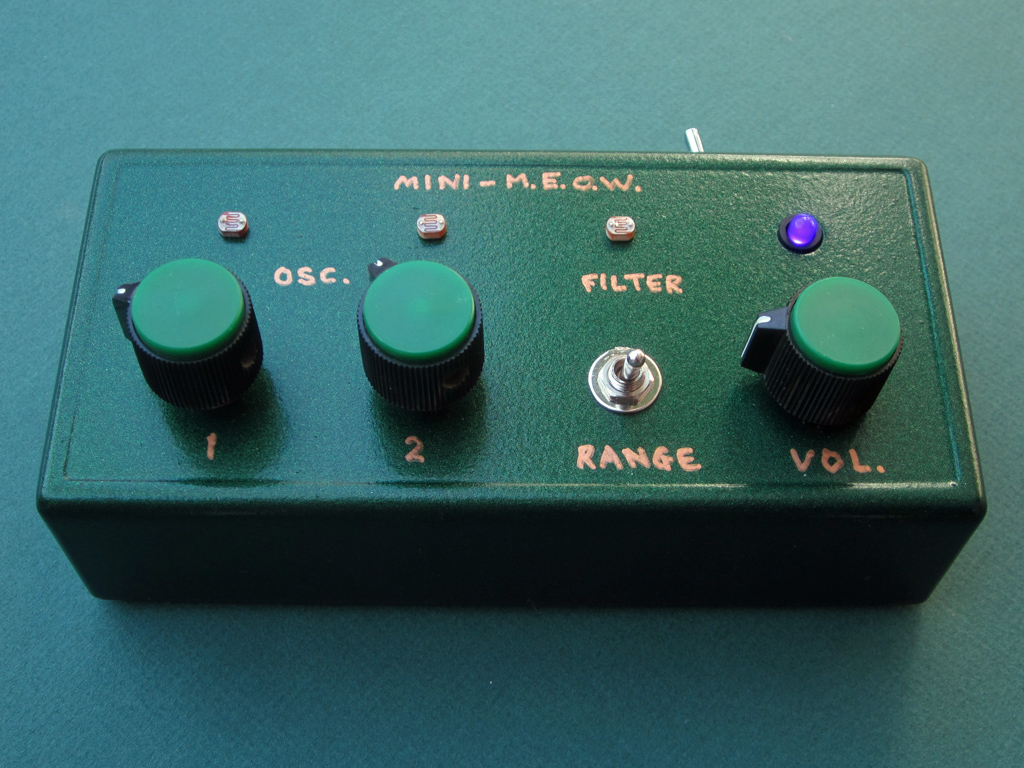
Mini-M.E.O.W.
M.E.O.W. could stand for "Melliloquent Effable Oscillator Weirdness". This box features two oscillators
made with P.U.T.'s (Programmable Unijunction Transistors) which give an interesting timbre reminiscent of a cat's meow.
They are also light-controlled, and then go through a light-controlled filter. The range switch changes
the capacitors for the oscillators, to help deal with different ambient light conditions.
This is based on the "Schrödinger II" circuit by "analog_backlash", with changes suggested by PHOBoS, found in the
electro-music forum here.
Originally this was supposed to be a more elaborate box, with lead & drone oscillators, CV input and an LFO to
control the filter, but I decided it wasn't worth the trouble, since the sounds would still be pretty limited and
thus I probably wouldn't use it much. The metallic green turned out darker than the spray can indicated, and doesn't
quite come out in the photo. The "on" LED is purple.
Completed December 2014.
Here is the Mini-M.E.O.W. demo video.
PharaohDrone
A simple but pretty cool little stereo drone circuit built into a garage-sale find.
The circuit is the
XOR Stereo Droner
by the amazing PHOBoS. I made two minor changes: 1. added a photo resistor
in series with one of the oscillators, and 2. removed a switch, making the "vactrol" permanent.
Since the box is quite snug, I had to put the potentiometers quite close together, so I needed small-diameter knobs.
I didn't have any to hand so I made some with cardboard and hot glue.
There's a funny thing that happens when one turns it off... it keeps running for quite a while. Oh, and it has flashing, glowing eyes!
Completed October 2014.
Here is the PharaohDrone demo video.
Animated Pinball Lightbox: "Faces".
Demo video here: vimeo.com/91720349. Completed April 2014
Front and back of a pinball backglass lightbox I made for a friend. The electronic circuit
controls general illumination, as well as randomly blinking lights and a chaser for the "big eye" which changes speed.
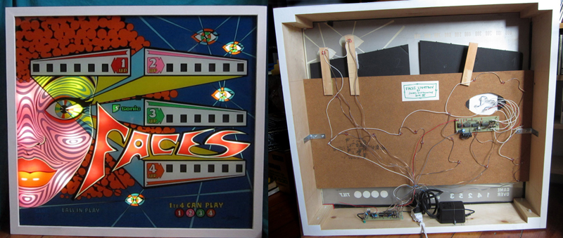
"Big eye" chaser light concentrator and circuit board detail. Maintains a slow speed for about 40 seconds then
suddenly runs fast, slowing down over about 40 seconds and returns to the slow speed.
This and the other lightboxes I made were part of the decor at the North Star pinball bar in Montreal, Canada.
The original Faces pinball machine was manufactured in 1976 in Spain by Sonic.
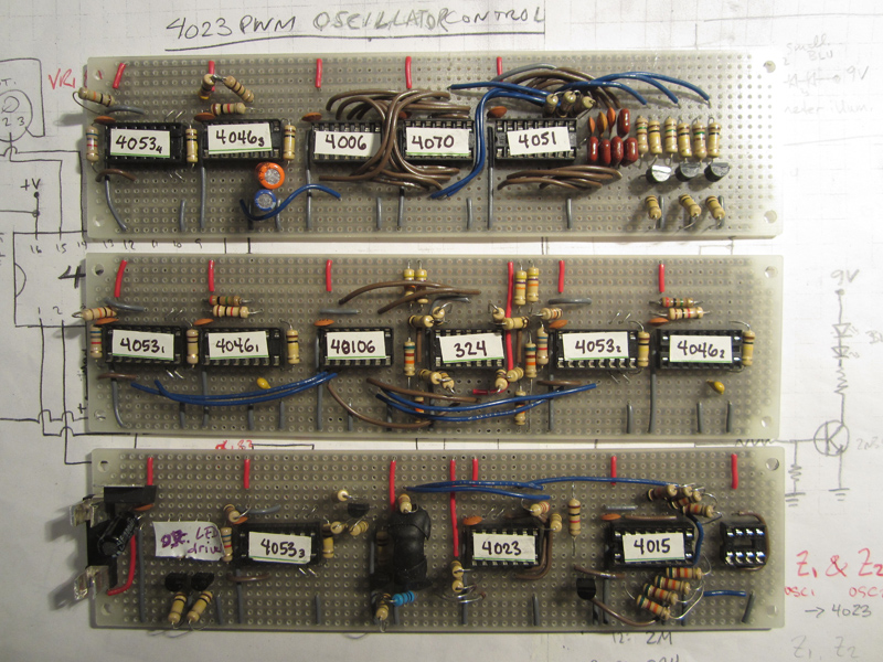
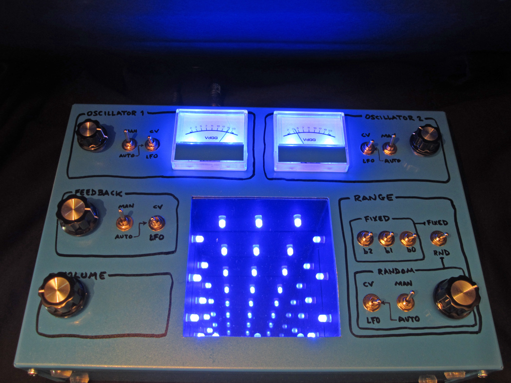
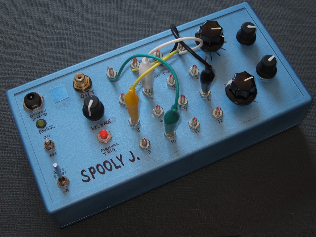
Pulse Witch 23
This box is based on a "pulse width oscillator" circuit by
Ryk M., wherein the 4
basic parameters can be adjusted manually or automatically (the latter via LFO or external CV). The idea is that
it can be played performatively, or used as a standalone installation.
The range section is a bit more complicated: 8 different capacitors can be selected manually via the 3-bit switches,
or pseudo-randomly, at a rate that can be controlled manually or automatically.
The cool feature of course is the infinity mirror.
The LEDs therein echo the state or value of the various sections, e.g. oscillator rate, feedback level and range choice.
The meters show the internal voltage level ultimately controlling the speed of the oscillators.
For Burroughs and the "23 enigma" watchers... the heart of the circuit uses a CMOS 4023 chip, the range on the meters go
from 2 to 23 (in prime numbers and VdGG units).
Completed November 2013.
Here is the Pulse Witch 23 demo video.
Here are the populated PCB's for the Pulse Witch 23. The layout's pretty clean here,
but then comes the panel wiring and things can get messy!
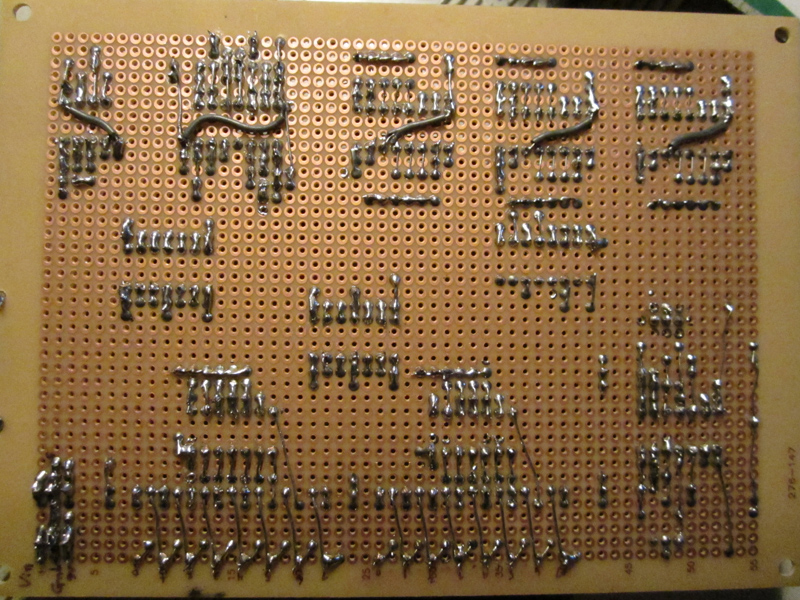
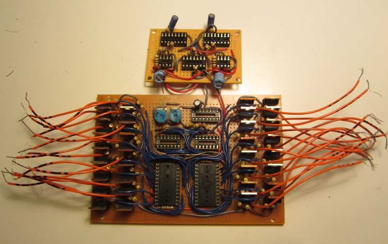
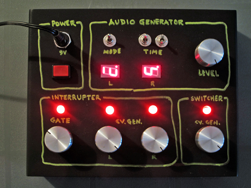
Sweet32 Automator A.K.A. Sweet32 Control Box Control Box
This box automates the Sweet32 Speaker Interrupter-Switcher Installation Thing Control Box (see below)
so that it can really be a standalone installation that changes its parameters over time. This includes a 2-channel
triangle wave oscillator, with either random tones, or slowly rising and falling tones. It can generate 256 different tones,
which are represented by the sideways LED displays. The box also generates CV and gate signals
to control the rate of the interrupters and switcher.
Completed May 2013.
See the Sweet32 Speaker Interrupter-Switcher Installation Thing page for more details.
PCB soldering, verso...
Usually I like to use bussed PCB's, but sometimes it's more practical to do the old perfboard-with-solder-pads thing.
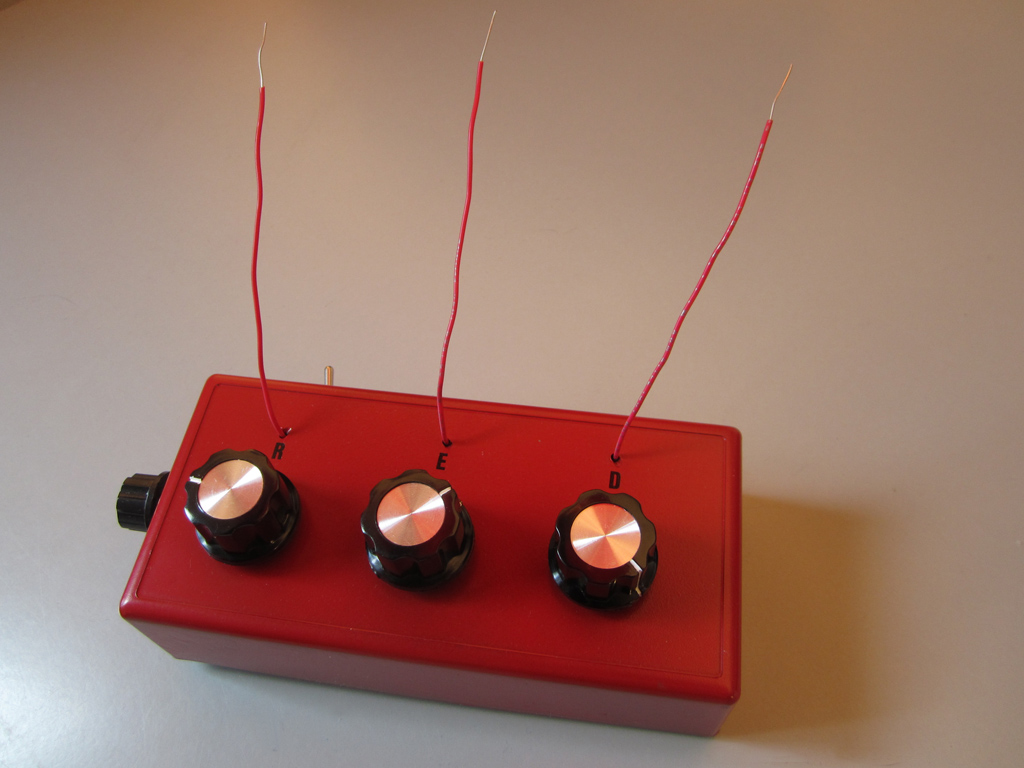
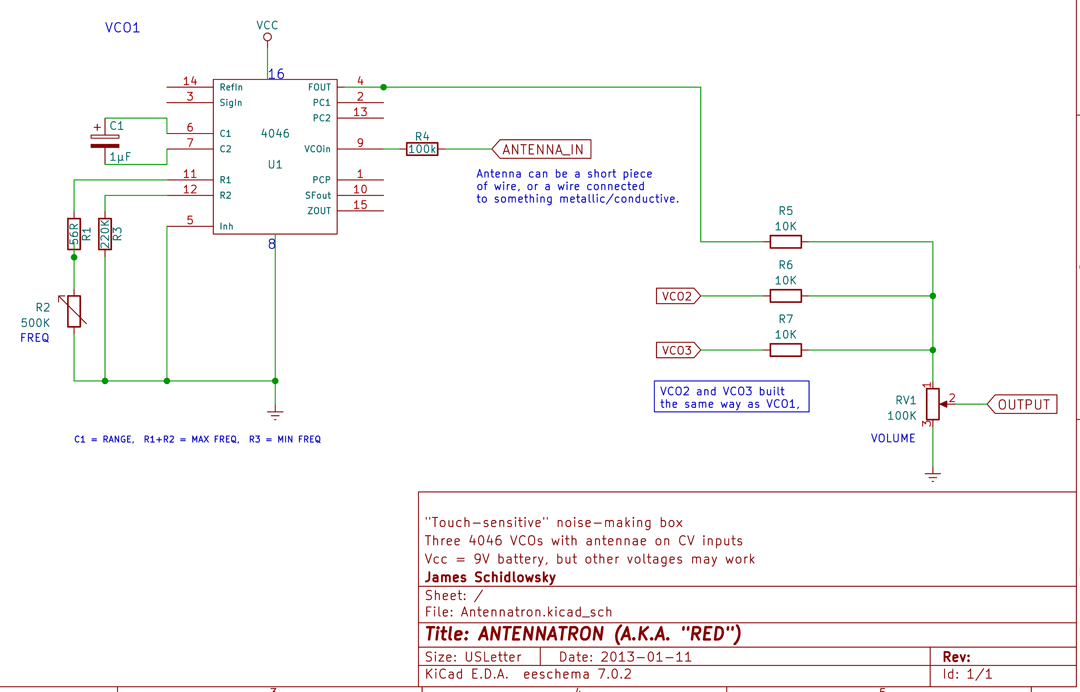
RED (Antennatron Noise Box)
Another silly little battery-operated noise box, made during a break from the big Sweet32 project. An accidental realization that putting an antenna
on the VCO input of a not-quite-properly hooked up 4046 produced noise, so I decided to run with the idea and have three such circuits interact.
The antennae pick up general random stuff, as well as proximity to living bodies. Completed March 2013.
Here is a quick RED noise box demo video.
Here is the Antennatron schematic
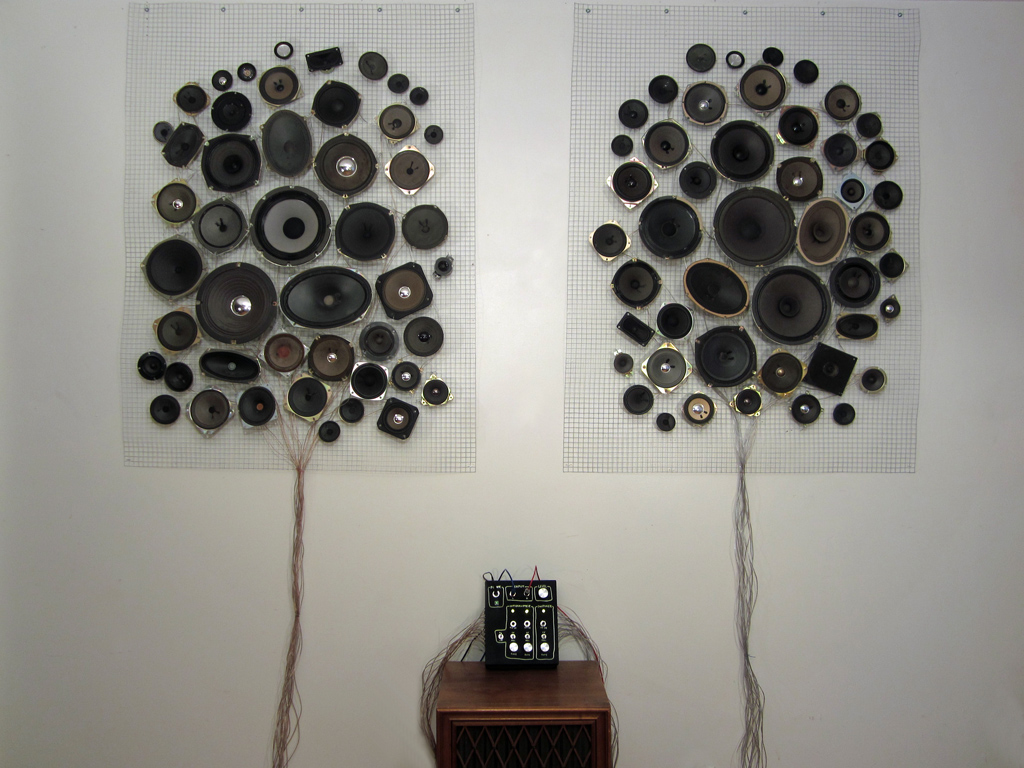
Sweet32 Speaker Interrupter-Switcher Installation Thing
(Ceci n'est pas la haute-fidelité)
After a few years of collecting speakers from stuff found in the trash, I finally got them off the floor and onto the wall.
There are 47 speakers per panel, but only 16 per panel are wired up to the control box. The box takes a 2
channel input and randomly selects which of the speakers the sound is directed to (for each panel). The rate
can be controlled by the knob, or via an external CV. There is also the optional interruption control on a
per-channel basis... this cuts the sound going to a panel according to the rate set via the knob (or external CV).
Alas, the box and the speakers are not very clean-sounding, so it is definitely lo-fi
Completed December 2012. A bit later, implemented a gate input to replace the on/off switch for the interrupter section.
See the Sweet32 Speaker Interrupter-Switcher Installation Thing page for more details.
No video could really demonstrate what this installation sounds like. Click on the image to
see the overall setup.
Here is the populated board for the control box...
Tea Candle Sound Box
A bit of a silly little box, made quickly to restore my sanity somewhat after spending an enormous amount of time
and energy on the Sweet32 Speaker Interrupter-Switcher Installation Thing, which failed massively when I first turned it on.
So, before getting down to serious debugging, I built this. Via the electro-music forum, I learned that the
flickering LEDs in dollar-store electronic tea candles produce sound. So I chose 3 of them that sounded good
together, and all the circuit does is mix the outputs through diodes and drive a speaker. Completed December 2012.
Here is a quick Tea Candle Noise box demo video.
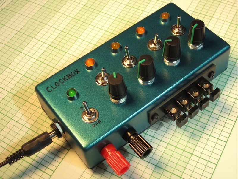
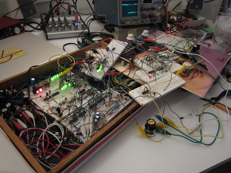
The Clockbox is a small utility device for making breadboarding simpler. I got tired of
building power sections and clock oscillators over and over, so I built this little box that gives me a regulated
and filtered 9V and four square wave clocks. Each oscillator has 3 different range capacitors, so the box can
produce frequencies ranging from about 0.01 Hz to 6300 Hz overall. With some alligator clips and/or wires, I can
plug it into my breadboard and away I go! Completed September 2012.
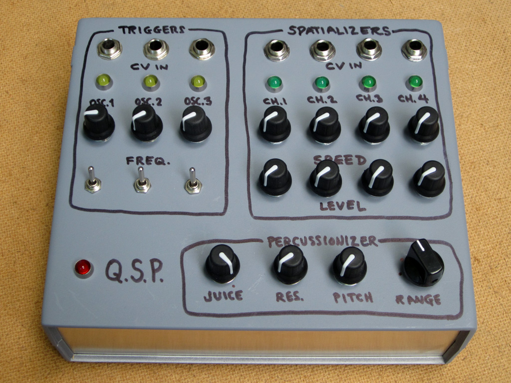
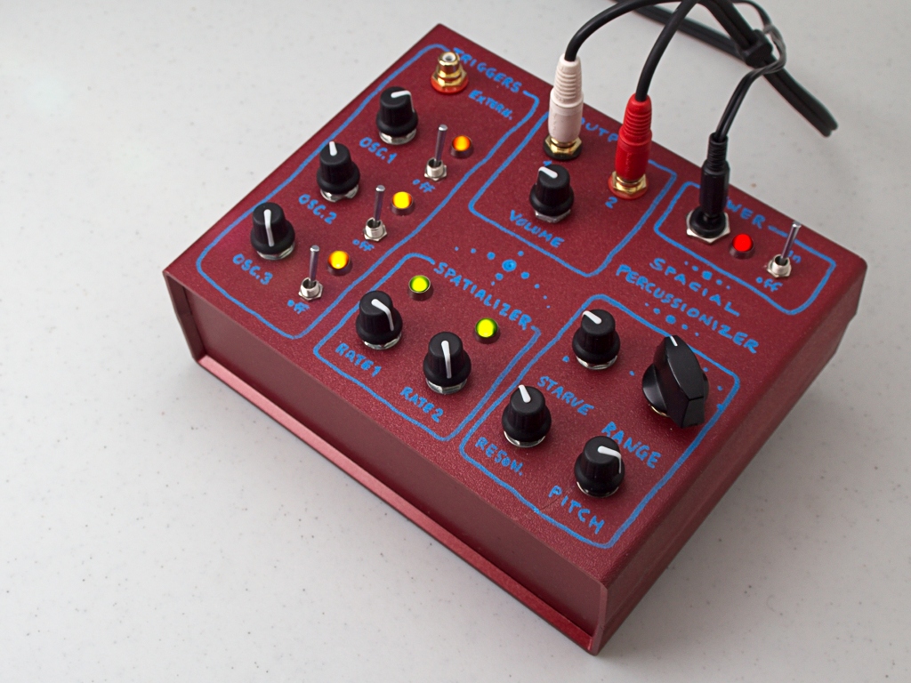
Quad Spacial Percussionizer
Customized version of the Spacial Percussionizer (see below) for my sound-maker friend
Alexandre St-Onge. He wanted a grey box with 4-channel output
instead of 2, as well as all the trigger and spatializing oscillators voltage controlled. The power switch and
output jacks are on the back side.
CMOS NAND gate “percussion”/noises generator with 4052
spatializers (with 4 positions per pair of channels).
Completed July 2012.
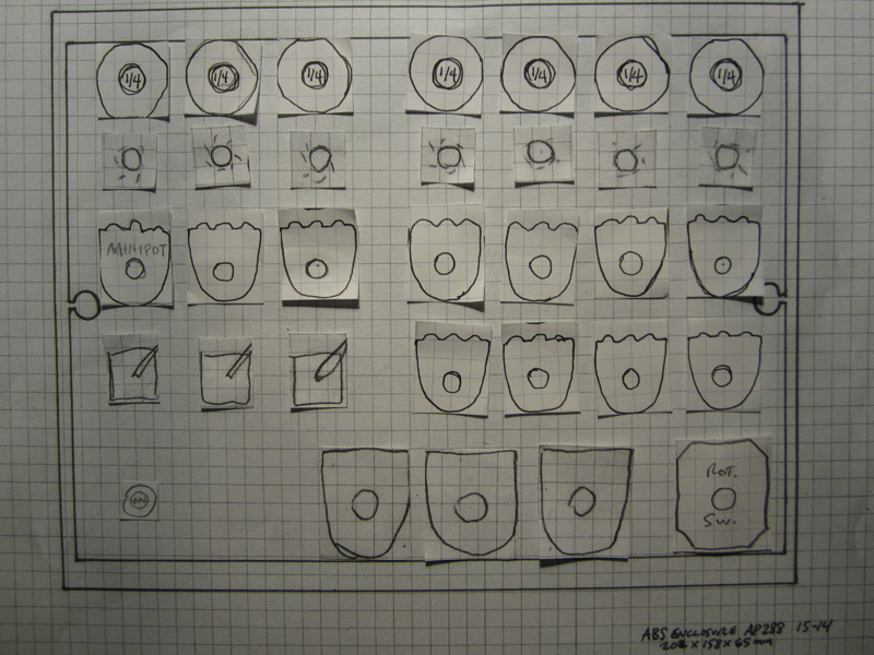
Here is the layout diagram. I use graph paper cutouts of the footprints of the different switches, pots and other
hardware, then try to find an ergonomic and logical layout that fits a given enclosure.
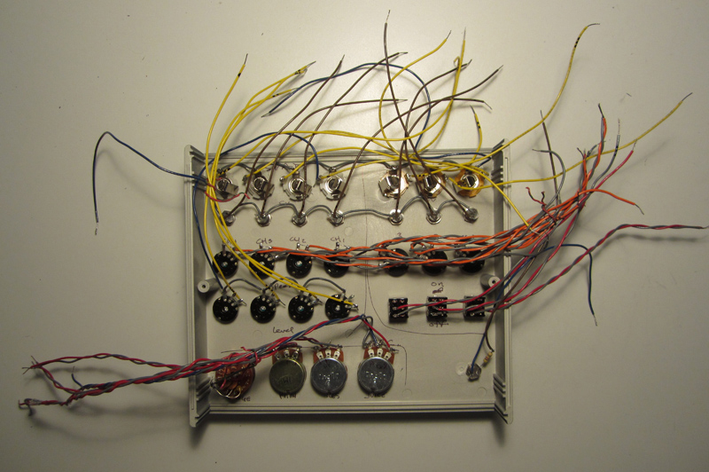
Panel wiring:
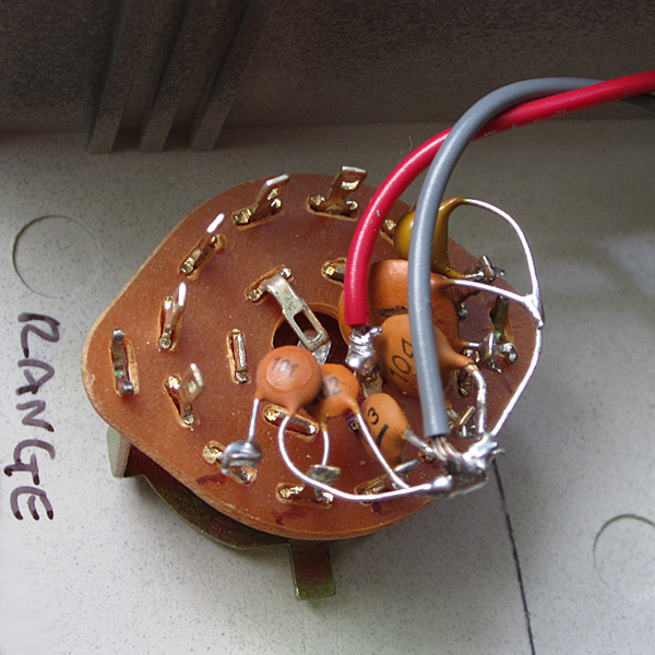
Detail of "range" rotary switch with 6 capacitors:
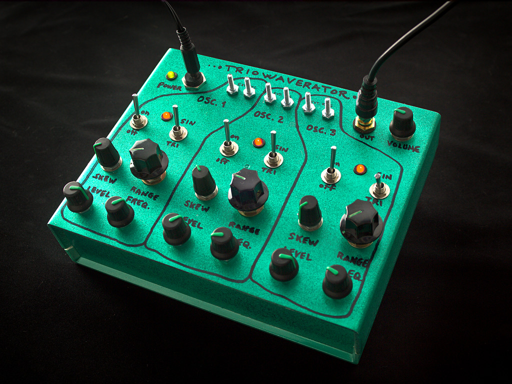
The Triowaverator
Triowaverator = Triple wave generator = 3 sine/triangle wave generators (XR8038 IC) with frequency, level and skew control.
Skew sortof makes a triangle into a sawtooth. The bolts are for attaching optional external variable resistors e.g. photoresistors,
which is what I used to make the “3 Candles, 3 Sines” video.
Completed February 2012. Photo by Linus Ouellet.
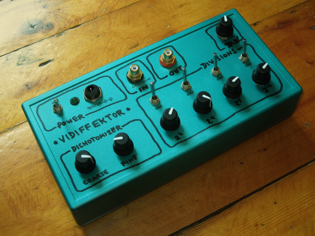
The Vidiffektor
The Vidiffektor is the odd box here, since unlike all the others, it mangles a video signal, rather than makes audio.
Basically, it slices up a composite video signal fed into the box, and adds several divisions of the signal back into it.
Two of these boxes were made, the other as a gift to my experimental filmmaker friend
Christine Lucy Latimer. Completed July 2011.
Here is the circuit schematic and discussion on electro-music.com.
A few people have built it and it is confirmed that it works for both NTSC and PAL.
When the circuit was still on the breadboard, I made this
Vidiffektor demo video (on youtube).
Here are more abstract videos using the Vidiffektor, including some by the aforementioned Christine:
www.vimeo.com/tag:vidiffektor.
"Lunetta" Synth prototype
2011. Synth based on logic chips, as proposed by Stanley Lunetta. A great way to start making
noise with electronics.
Visit the Lunetta forum on electro-music.com
for more info/inspiration. Alas, I never got around to finishing this beast.
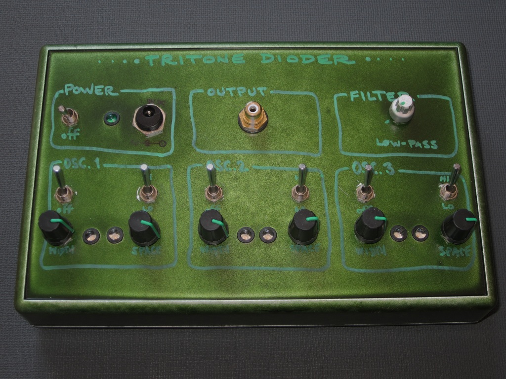
The Tritone Dioder
The Tritone Dioder is simply three squarewave oscillators mixed together via diodes. Also, the duty cycle of each wave
can be changed. Completed October 2010. Later, the potentiometers (which were cheap junk) were replaced (and with larger knobs, which
changed the aesthetic -- which was pretty botched to begin with).
Here is the Tritone Dioder demo video (on youtube).
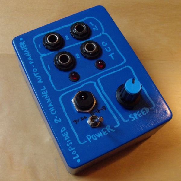
Note that it involves two phaser pedals and another very simple box I made called the Lopsided 2-Channel Auto-Panner.
The Quadratic Cascading Intersidereal Noisificator
The Quadratic Cascading Intersidereal Noisificator (or Le Bruitificateur intersidéral quadratique en
cascade in french) was based on a circuit in the above-mentioned Nicolas Collins book. It is based on a cascading
series of 4 oscillators made using a 4093 NAND gate CMOS chip, wherein the first oscillator is gated by a 555
oscillator, which itself can be affected with another 555 (called the Saccadeur -- which can sort of be
translated from french as stutterer or jerker). Completed August 2010.
Here is the The Noisificator demo video (on youtube).
It is now owned by my sound artist/noisemaker friend
Magali Babin after making a few changes she requested (trig in jack replaced
by volume control, RCA out jack replaced by 1/4" jack -- these do not appear in the photo).
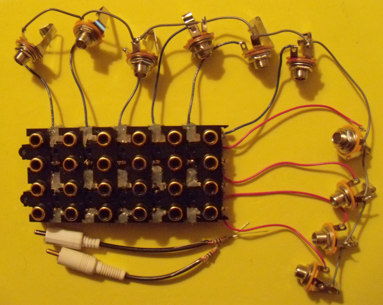
4x6 Patch Matrix
2010. Made from six 1x4 RCA jack blocks (scored at Active Surplus in Toronto (R.I.P.))
hot-glued together and using resistor-shorted RCA plugs to make the connections.
Also from the early days. I lost interest because I stopped using a lot of effects pedals and I didn't really have
much use for it. So I never got around to putting it into a more durable enclosure.
The Lopsided 2-Channel Auto Panner box.
2010. Not a very good circuit, but it was in my early days of making stuff.
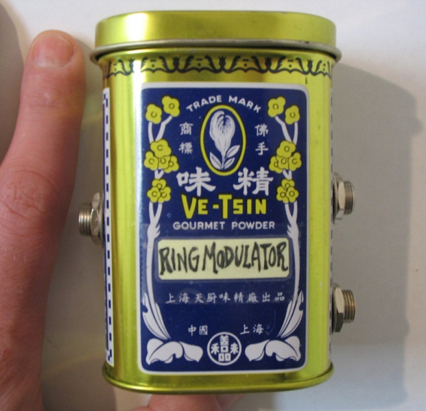
2005. Classic Passive Ring Modulator, using 4 diodes and 2 transformers. Built into a can of "gourmet powder"
which is really M.S.G. (which I did not eat).


